Beginner electronics guide
Your First Electronics Project: Build a Simple LED Circuit
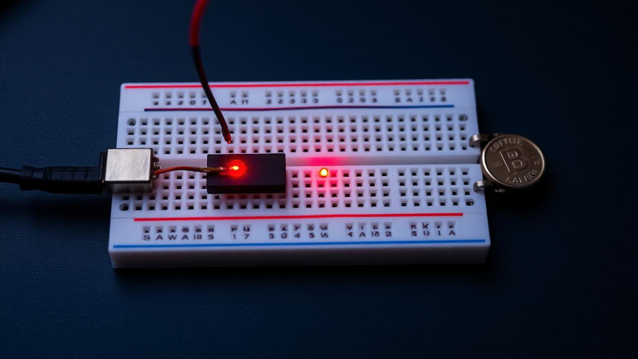
Every electronics journey starts with the same small victory: making a light turn on because you wired it that way. A single LED circuit takes about ten minutes and teaches you three ideas you will use in every project afterwards — current, polarity and how a breadboard is wired underneath.
What an LED circuit actually is
An LED (light-emitting diode) converts current into light. Unlike a bulb, it does not regulate how much current it takes — give it too much and it burns out. So an LED circuit is really two components in series: the LED, and a resistor whose job is to hold the current down to a safe level. That is the whole circuit. Power in, through the resistor, through the LED, back to ground.
Parts you'll need
| Part | Qty | Est. cost |
|---|---|---|
| Breadboard (half-size, 400 tie points) | 1 | $4 |
| 5 mm LED (red is the most forgiving) | 1 | $0.20 |
| 220 Ω resistor (1/4 W) | 1 | $0.10 |
| Male-to-male jumper wires | 2 | $1 |
| Power: 2x AA battery holder, or a 5 V microcontroller pin | 1 | $3 |
| Estimated total | ≈ $8 |
Sizing the resistor with Ohm's law
Ohm's law says R = V / I. For an LED you use the voltage the resistor has to absorb — the supply voltage minus the LED's own forward voltage — and the current you want through the LED.
R = (Vsupply − VLED) / I
R = (5 V − 2 V) / 0.015 A = 3 V / 0.015 A = 200 Ω
A red LED drops roughly 2 V and is happy at about 15 mA. 200 Ω is not a standard value, so you go to the next one up: 220 Ω. Rounding up is always the safe direction — it means slightly less current and a slightly dimmer, longer-lived LED. Blue and white LEDs drop around 3 V, so the same maths gives about 130 Ω; a 150 Ω resistor works well there.
Step-by-step wiring
Push the LED into the breadboard so its two legs sit in different rows. The long leg is the anode (+), the short leg next to the flat notch is the cathode (−).
Put one end of the 220 Ω resistor in the same row as the long leg, and the other end in an empty row. Order does not matter electrically — the resistor can sit on either side — but this keeps the layout readable.
Run a jumper from the free end of the resistor to the breadboard's + rail.
Run a second jumper from the LED's short leg to the − rail.
Connect your power source: + to the + rail, ground to the − rail. The LED lights immediately.
Common mistakes
- Skipping the resistor. An LED across 5 V with nothing to limit current draws far more than it can survive and dies in seconds.
- LED in backwards. It is a diode, so it only conducts one way. Flip it and try again — reversing it does no damage at these voltages.
- Legs in the same breadboard row. Rows of five holes are connected internally, so both legs in one row short the LED out and nothing lights.
- Assuming a dead circuit means a dead LED. Nine times out of ten it is a rail not connected, or a jumper one hole off.
What to try next
- Add a pushbutton in series so the LED only lights while the button is held.
- Swap the battery for a microcontroller pin and blink the LED in code — that is the classic first program.
- Wire three LEDs, one per pin, and sequence them into a traffic light.
- Replace the fixed resistor with a potentiometer to dim the LED by hand.
Once the LED lights reliably, you have a working power rail, a known-good breadboard and a way to test any pin. Almost every beginner electronics project builds on exactly that.
Ready for a full project?
Answer five quick questions and get a beginner build matched to your experience, time and budget.